Hall Effect Sensor Circuit Arduino

Noted Hall Effect Sensor Arduino Program Hall Effect Arduino Sensor

Building Gizmos With Arduino Latching Hall Effect Sensor Hall Effect Arduino Arduino Sensors

Interfacing Hall Effect Sensor With Arduino Arduino Hall Effect Sensor

Hall Effect Sensor Circuit In 2020 Hall Effect Sensor Circuit

How To Use A Hall Effect Sensor With Arduino Education Maker Pro Hall Effect Arduino Sensor

Hall Effect Sensor Circuit Schematic Hall Effect Sensor Humidity Sensor

The vout or signal pin of the hall effect sensor is connected to the arduino s interrupt pin digital pin 2.
Hall effect sensor circuit arduino.

Hall Effect Sensor With Arduino Circuit And Code Arduino Projects Arduino Wifi Arduino

Hall Effect Sensor To Sense Magnetic Proximity Arduino Hall Effect Circuit Diagram

Ac Current Measurement Using Arduino And Hall Effect Sensor Acs712 Arduino Hall Effect Sensor
A3144 Hall Effect Sensor Pinout Working Alternatives Datasheet Hall Effect Sensor Electronic Circuit Design

Interfacing Acs712 Current Sensor With Arduino Measure Current With Arduino Measuring Current With Arduino Arduino Sensor Arduino Circuit

Noted Hall Effect Current Sensor Circuit Hall Effect Sensor Arduino

Ac Current Measurement Using Acs712 Hall Effect Current Sensor And Arduino Arduino Hall Effect Arduino Projects

How To Build A Hall Effect Sensor Circuit Hall Effect Sensor Hall

For My Other Project For Work I Had To Measure The Rotational Speed Of Rotor In Revolutions Per Minute Rpm Of One Hall Effect Arduino Arduino Motor Control

How To Measure Ac Current Using Hall Effect Sensor With Arduino Or Other Common Microcontrollers With Images Hall Effect Arduino Arduino Projects

Arduino Rpm Hall Effect Arduino Arduino Projects Hall Effect

Fan Rpm With Internal Hall Effect Sensor And Arduino Intro To Hardware Interrupt And Lcd Display Hall Effect Arduino Sensor

A3144 Hall Effect Sensor Pinout Hall Effect Electronic Circuit Projects Electronics Projects Diy

Hall Effect Sensor Us1881 Latching 5 Pcs Hall Effect Arduino Electronic Engineering

How To Measure Ac Current Using Hall Effect Sensor With Arduino Or Other Common Microcontrollers Hall Effect Arduino Sensor

How To Build Your Own Anemometer Using Reed Switches Hall Effect Sensor And Some Scraps On Nodemcu Part 1 Hardware Anemometer Hall Effect Arduino

Simple Short Sketch Example Of Communication Between Two Nrf24l01 Modules Connected To Two Arduino Unos Arduino Projects Arduino Wifi Arduino

Hall Effect Sensor As Limit Home Switches Arduino Programming Arduino Programming Arduino Hall Effect
Https Encrypted Tbn0 Gstatic Com Images Q Tbn 3aand9gcrajt S9bgw76irubyzfxspg9wy6ma Afrotdh35fhq0fpv3clf Usqp Cau

Hall Effect Sensor Switch Magnetic Detector Module For Arduino Motor Arduino Motor Hall Effect Sensor

Hall Effect Sensor Pinout Hall Effect Sensor Arduino

Water Flow Sensor Arduino Circuit Arduino Arduino Circuit Arduino Projects

Observe The Magnetic Field Integrity And Polarity By Using Arduino And A 3144e Hall Effect Sensor Magnetic Field Hall Effect Tester

Use A Hall Effect Sensor To Detect The Presence Of A Magnet And Make A Speedometer A Burglar Alarm And More Hall Effect Arduino Sensor

Arduino Based Magnetic Field Measurement Arduino Electronics Projects Microcontrollers

Oh137 Arduino Hall Switch Tutorial Arduino Arduino Sensors Electronics Circuit
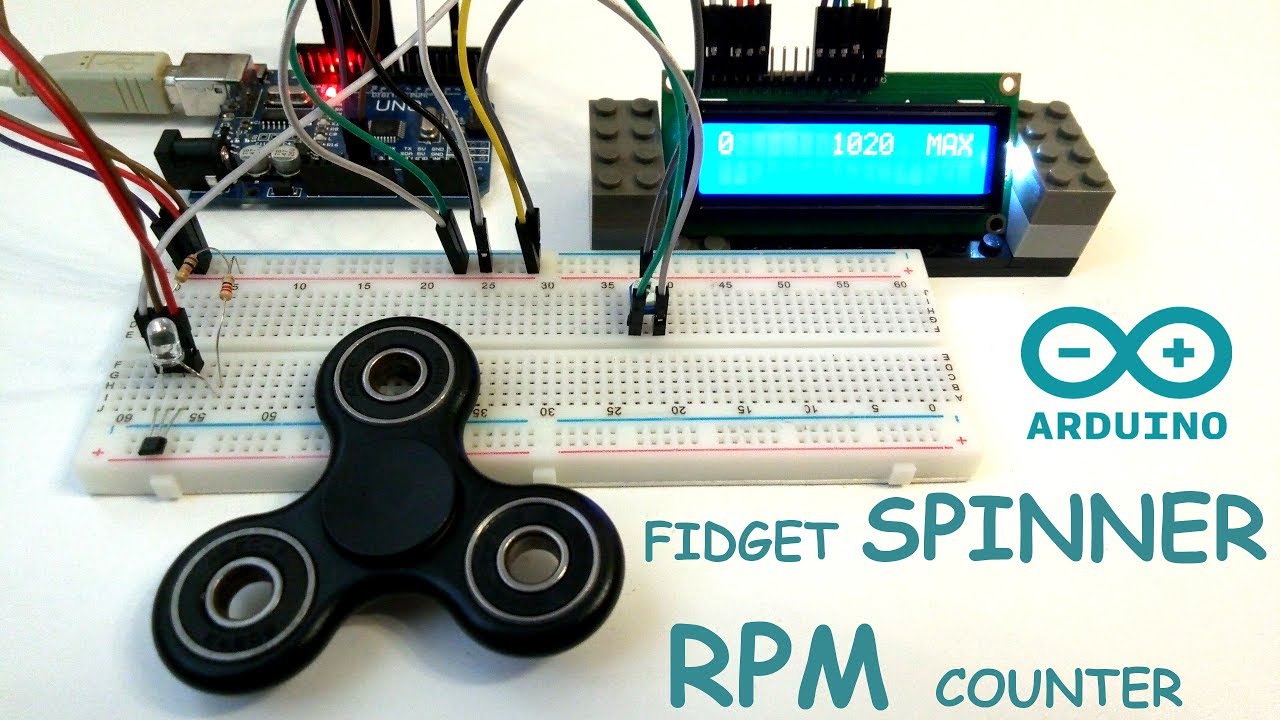
Image Result For Hall Effect Sensor Arduino 1344 Fidget Spinner Arduino Hall Effect

How To Use Hall Effect Sensor With Arduino Working Hook Up Guide And Relay Control In 2020 Hall Effect Arduino Sensor

How To Use Hall Effect Sensor With Arduino Working Hook Up Guide And Relay Control In 2020 Hall Effect Arduino Sensor

Arduino Tutorial Hall Effect Sensor From Banggood Com And Arduino Uno Youtube Hall Effect Arduino Arduino Sensors

How To Use Hall Effect Sensor With Arduino Hall Effect Arduino Projects

Arduino Magnetometer Arduino Projects Arduino Useful Arduino Projects


Pin On Projects To Try

Water Flow Sensor Measure On Display On 16x2 Lcd Hackster Io Electronic Circuit Projects Sensor Arduino

Circuit To Read Data From A Water Flow Sensor Using Arduino Read More At Http Www Haberocean Com 2015 05 Circui Arduino Arduino Projects Diy Reading Data

Introduction Hall Effect Switches Sensors Circuits Tutorial Hall Effect Circuit Sensor

Inductive And Hall Effect Rpm Sensors Explained Kiril Mucevski Linkedin Hall Effect Sensor Automotive Electrical

Fan Rpm With Internal Hall Effect Sensor And Arduino Intro To Hardware Interrupt And Lcd Display 3 Steps With Pictures Hall Effect Arduino Sensor

How To Use Hall Effect Sensor With Arduino Working Hook Up Guide And Relay Control In 2020 Hall Effect Arduino Sensor

How To Use Hall Effect Sensor With Arduino Hall Effect Arduino Being Used

Simplified Arduino Ac Current Measurement Using Acs712 Hall Effect Sensor Arduino Hall Effect Electronics Projects

Circuit Diagram For Magnetic Field Measurement Using Arduino Arduino Magnetic Field Arduino Projects
Https Encrypted Tbn0 Gstatic Com Images Q Tbn 3aand9gcto1rkcteri1c7ecbx6bvb7a8jxu9lopsaqvc60tqw Usqp Cau
Source : pinterest.com
